Seco® Octomill™ 06 : more than just a face mill
Octomill™ 06 : Seco's Face Mill offers High Performance and User-Friendly DesignNew indexable face milling cutter: Seco® Octomill™ 06
The cutting tool market focuses heavily on developing new double-sided solutions for indexable milling cutters. Single-sided solutions however are often preferred and requested due to higher edge utilization, lighter cutting behavior and broader material coverage.
Seco’s new Octomill™ 06 (generation) tackles the major challenges of single-sided face milling inserts, with easy and secured insert handling. Combine the best of two worlds for indexable face milling cutters: the benefits of a single-sided system with similar insert handling of a double-sided system.
The indexable face milling cutter Seco® Octomill™ 06 keeps strength and overcomes weakness by merging the light cutting behavior of an OF-style solution and the cutting edge strength / robustness of an OD-style solution.
Inline Content - Gridded Links
Tags: '9d081510-9cd9-5bb0-8a03-25229349cb69', 'ed313ff4-3f00-550d-9a79-b0e12499e906', '242e615d-a809-5f7c-8949-0f4ad787b2cd', 'b4985bc6-853c-5998-8d2c-74b1c2f465b7'
Go to products
How to choose the right cutter option?
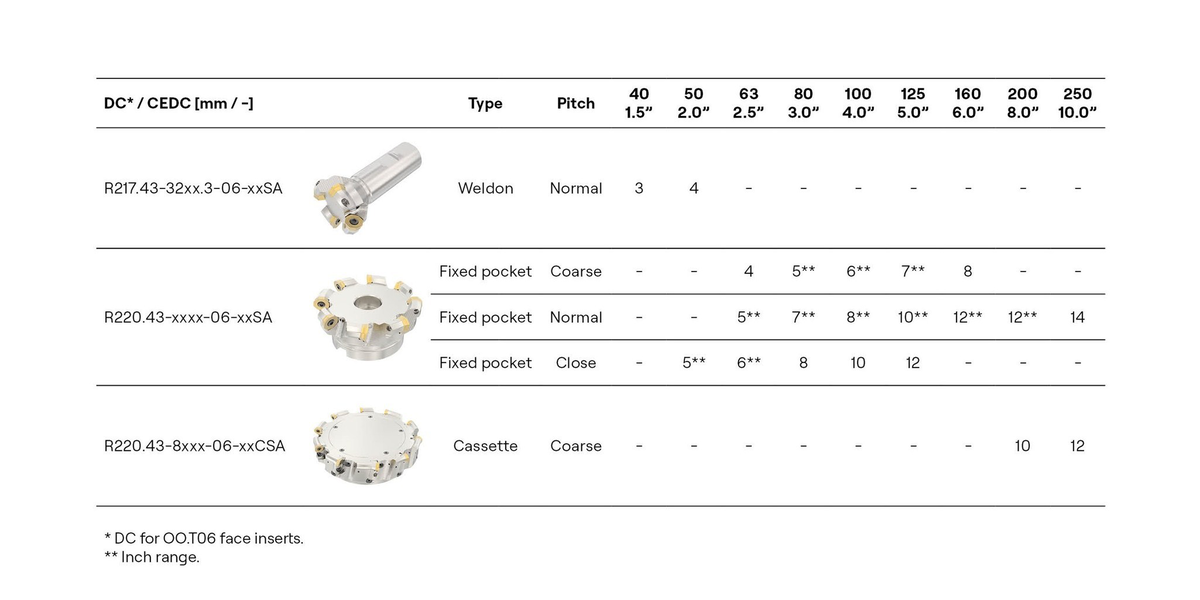
When choosing a face milling cutter, it’s specifications are important for you to know. Seco’s new Octomill™ cutter offering includes 3 pitches in the core diameter range from 63 – 125 mm. Ideal to adjust the tooling to your application and challenges. Depending on the cutter pitch and radial engagement multiple inserts are in contact with the workpiece and impacting the risk of vibrations.
Coarse pitch
- Problem solver for unstable set ups and low power machines due to the lowest cutting forces
- Achieve comparable removal rates with increased dept of cut or feed per tooth.
- Improve price performance ratio thanks to reduced number of inserts per cutter.
- Differential pitched design reduces harmonics during machining
Normal pitch
- First choice for most applications due to good balanced between cutting forces and performance.
- Differential pitched design reduces harmonics during machining
Close pitch
- Highest productivity and tool life in stable set ups
- Remain acceptable chip thickness for certain geometry and materials.
Cassette cutter
- Versatility of adjustment to eliminate or reduce axial runout
- Ability to replace one pocket by replacing a cassette instead of entire cutter body in case of a damage
- Disadvantages are more spare parts, limited number of teeth and slightly higher radial run out due to more parts in the tolerance chain.
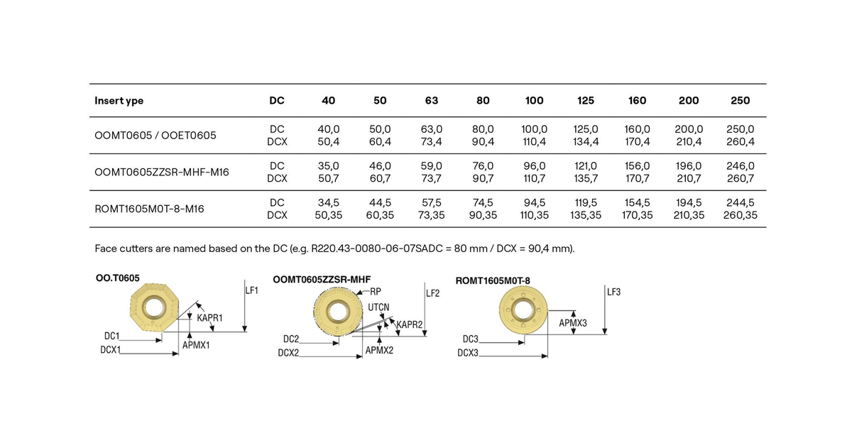
Due to the shared pocket of multi-insert approach, an insert change from face to round has an impact on the outer dimensions of the indexable face milling cutterr. The table lists the nominal DC and DCX values depending on the insert shape as well as cutter choice. Consider that round and high feed cutters are always dimensioned based on the maximum outer cutting diameter called DCX. Face milling cutters are always designed based on the cutting diameter DC.
There is no 1-to-1 dimensional alternative available of the Octomill™ ROMT1605 in comparison to the existing R217/220.29I range. Choose a smaller or bigger cutter option to tackle round insert applications.
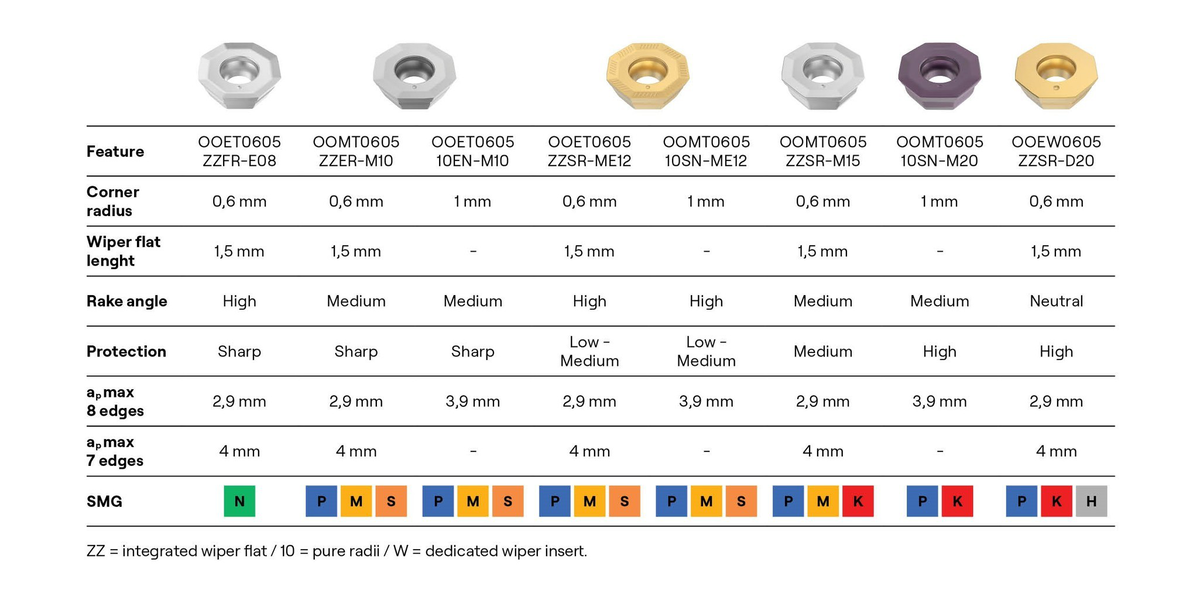
Insert range for the Seco® Octomill™
The indexable face milling cutter can be used to machine all materials on highest performance levels. This material versatility is comparable with the Quattromill range. The insert range offers highest performance level in each material due to dedicated geometry and grade combinations.
The diagram highlights the first-choice geometry as well as suitable alternatives per SMG area depending on the targeted application. The left side of the diagram covers applications that require a freer cutting geometry due to potential weak set ups or softer materials. Applications with more vibrations, strong set ups as well as harder materials require more protected geometries to withstand these cutting conditions.
| Geometry | SMG | Application | Comment |
OOET0605
ZZFR-E08
| N | Roughing Finishing | Sharp and high rake angle, ideal for nonferrous materials as well as softer sticky materials.
Problem solver in challenging finishing applications
|
OOET0605
ZZER-M10
| M,S,P | Roughing Finishing | Precision ground insert with sharp and moderate rake angle. Made for roughing to finishing of challenging materials as M and S, but also alternative for low alloyed steels. Ideal for finishing application with demanding optical surface finish appearance, due to excellent run out and sharp edge that reduced built up edges leading to smeared surfaces. |
OOMT0605
10EN-M10
| M,S,P | Roughing | Economical alternative to the ground insert. Made for roughing of challenging materials as M and S, but also alternative for low alloyed steels. Missing wiper flat reduces tool pressure which is great for weak set ups and can be generate a consistent optical appearance at higher numerical values in case of finishing. |
OOET0605
ZZSR-ME12
| P,M,S | Roughing Finishing | Precision ground insert with smaller protection chamfer and high rake angle. Made for roughing and finishing of P, M and S at higher feed rates versus the M10 geometry. Can be also used as a freer cutting and more precise alternative to M15. |
| OOMT060510SN-ME12 | P,M,S | Roughing | Economical alternative to the ground insert. Made for roughing and finishing of P, M and S at higher feed rates versus the M10 geometry. Can be also used as a more free cutting alternative to M15. |
OOMT0605
ZZSR-M15
| P,K,M | Roughing Finishing | Protected and moderate rake angle.
First choice geometry for many applications. Can be used for finishing and roughing at moderate feed rates in a broad material mix. Thanks for the direct pressed tolerance a great price-to-performance choice.
|
OOMT0605
10SN-M20
| P,K | Roughing | Protected and moderate rake angle.
Free cutting roughing geometry for higher feed rates without wiper flat. Made for P and K materials.
|
OOEW0605
ZZSR-D20
| K,H,P | Roughing Finishing | Robust geometry that can handle high feed rates, interrupted cuts and hard materials while remaining light cutting behavior. |
Recommendations for speed and feed and geometries
The diagram highlights the first-choice geometry as well as suitable alternatives per SMG area depending on the targeted application. The left side of the diagram covers applications that require a freer cutting geometry due to potential weak set ups or softer materials. Applications with more vibrations, strong set-ups as well as harder materials require more protected geometries to withstand these cutting conditions.
Discover the Seco Face Milling range
Discover the Seco Face Milling Range