11 tool wear patterns when machining with end milling cutters
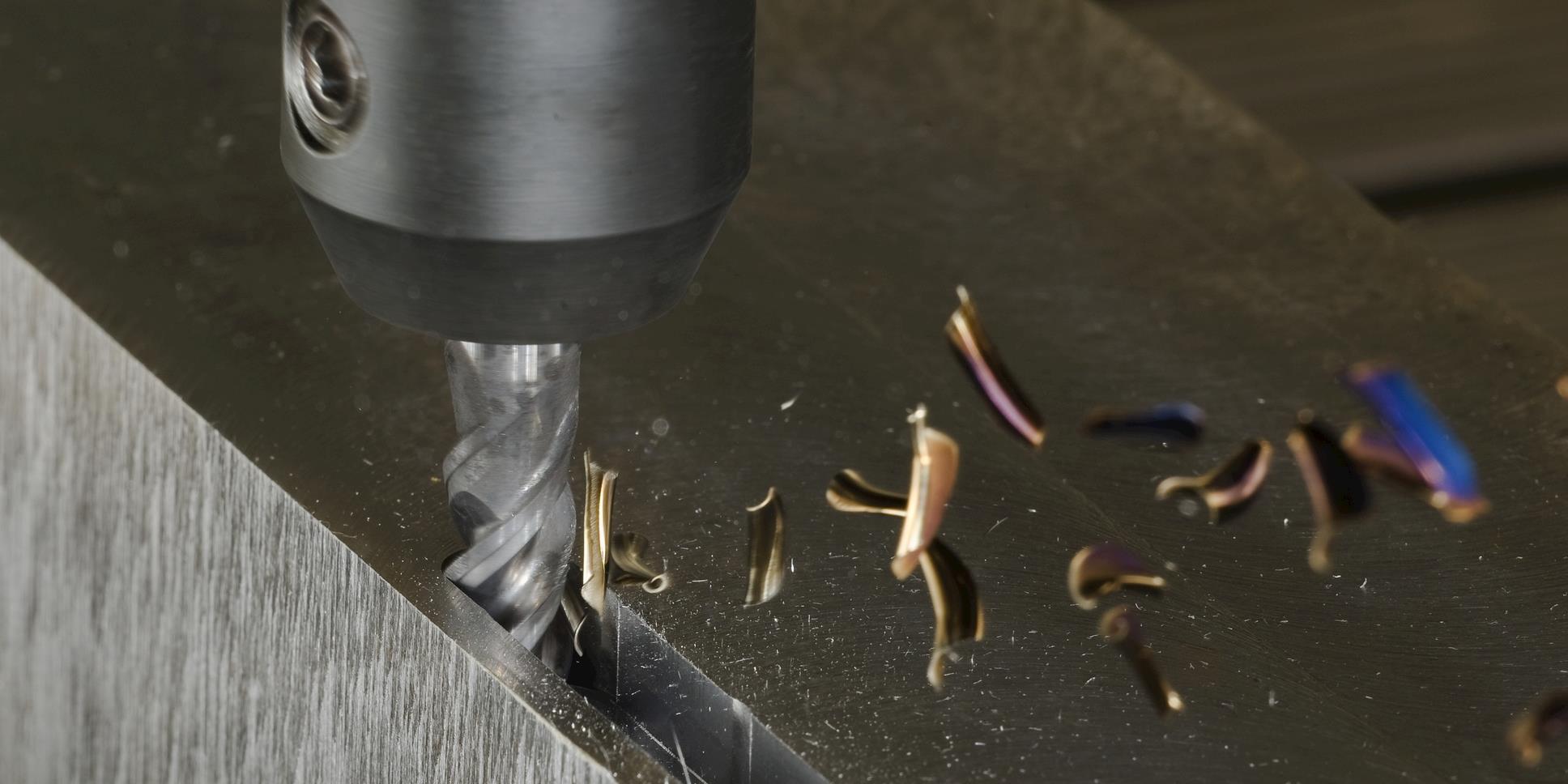
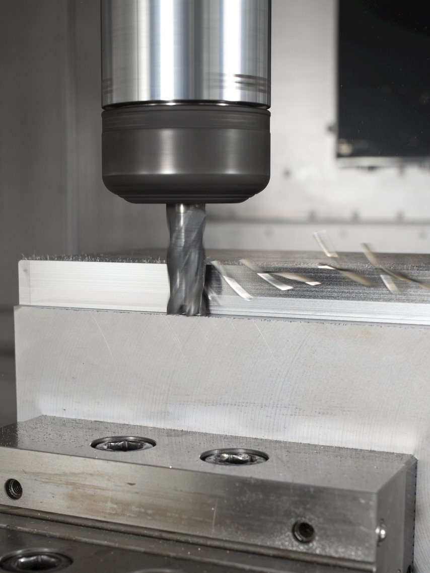
Identify and prevent wear issues on your carbide end mills. Here are some troubleshooting tips for making your tools last longer.Each wear pattern tells a story about your machining process. Some are expected, like flank wear, while catastrophic fractures are warnings you don’t want to ignore. Here we break down the most common types of wear, what causes them, and how to troubleshoot or prevent them. Because the more you know, the longer your tools last.
Being predictable and dependable, flank wear is the ideal wear pattern you want to see on your tools. Saying that, it shouldn’t happen too quickly as this is considered a problem.
Flank wear is a relatively uniform abrasion along the cutting edge. Occasionally, metal from the workpiece makes it look bigger than it is, but you can expect this kind of wear in all materials and if your tool doesn’t fail by another type of wear, this will be the one to end its life.
- Increase the coolant concentration
- Check and balance the feed rate with the type of flank relief
- Check if the balance of cutting speed and feed is correct
- Verify that the tool is the best choice for the material
Although not that common in milling operations, crater wear is a combination of heat damage, material breakdown and abrasive wear. And if you want a more technical explanation – the heat from the chips decomposes the tungsten carbide grains in the substrate and carbon leeches into the chips (diffusion), wearing a crater on the rake face of the tool.
- Increase coolant concentration
- Balance the feed rate with the type of rake relief
- Check if the balance of cutting speed and feed is correct
- Verify that the tool is ideal for the material
There is a more specific type of crater wear called point cratering. This wear pattern is caused by the erosion of a localized area on the cutting edge. It is caused by a combination of chemical reactions and a lot of heat and abrasion from the formed chip.
- Verify your tool selection
- Use an adequate amount of coolant
- Reduce the cutting speed
- Reduce the feed
Chipping is basically a fracturing of the cutting edge. It is typically associated with stability problems and vibrations.
- Keep the tool length as short as possible
- Make sure your set-up is rigid
- Check that the tooling is balanced and run-out is within specification
- Confirm the cutting parameters are correct
- Make sure the tool is suited to the material
- Ensure the chips are being evacuated properly
There is a specific type of chipping called point chipping. Mostly associated with stability issues but can also appear when chatter occurs if, for example, the milling strategy isn’t appropriate.
As well as going through all the troubleshooting steps above, you can also:
- Check the cutting parameters, as low cutting speeds will lead to chatter
- When machining corners, use the trochoidal milling method

A built-up edge is formed when the workpiece material sticks to the rake face of the milling cutter. Often, the material deposited on the tool’s surface can be caused by pressure, friction and/or inadequate cutting conditions.
- Increase the cutting speed
- Increase the coolant concentration and volume
- Use a tool suited to the material – flute design, helix, coating and surface condition are important
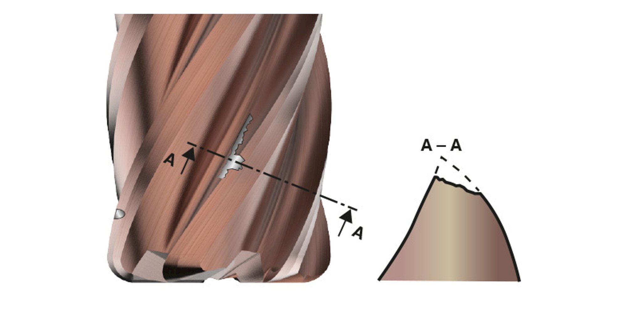
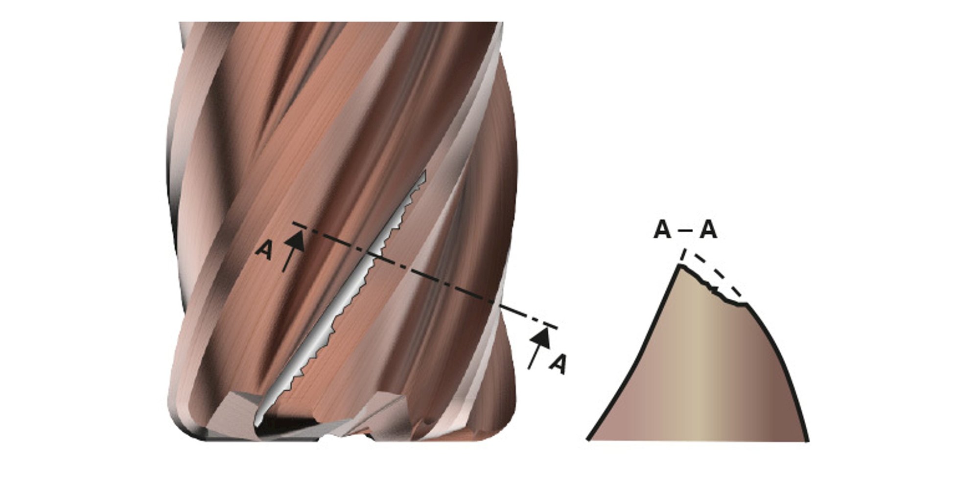
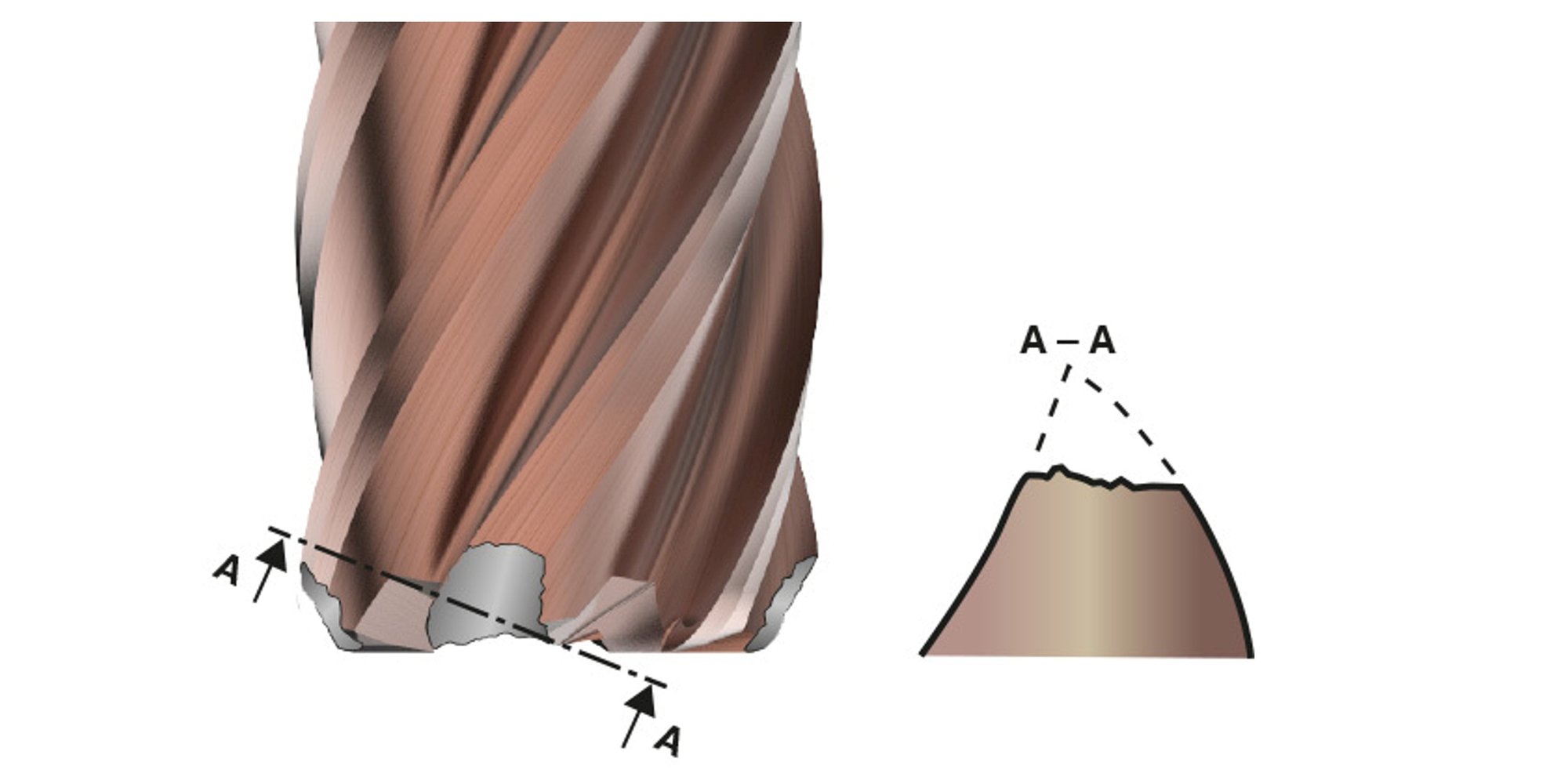
Notching happens when the carbide erodes in a specific area on the cutting edge. In most cases this is caused when the workpiece rubs against the tool.
- Verify the geometry of the end mill
- Vary the depth of cut if possible
- Reduce the cutting speed

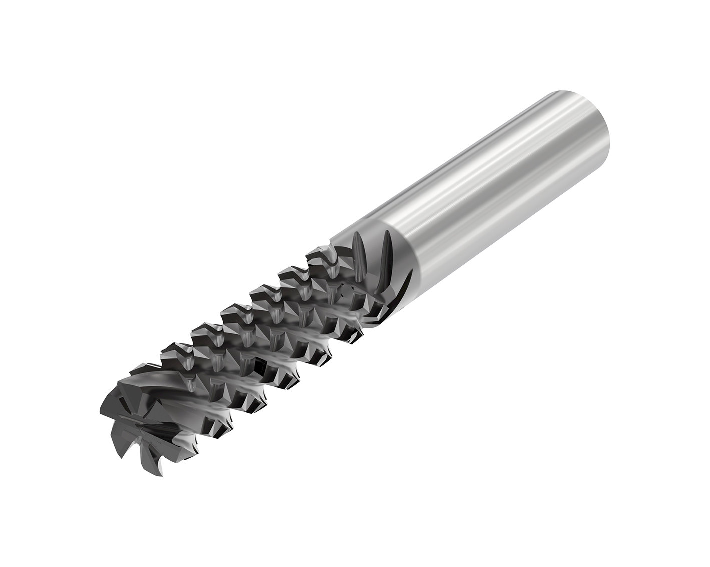
Not to be confused with notch wear as the two can look very similar, ineffective chip evacuation will also cause the milling cutter to be damaged along the cutting edges.
- Reduce the depth of cut to allow for proper chip removal on dual core tools
- Verify the tool against the material
- Verify that the tool is the best choice for the material
- Increase the helix angle
- Reduce the feed rate or depth of cut
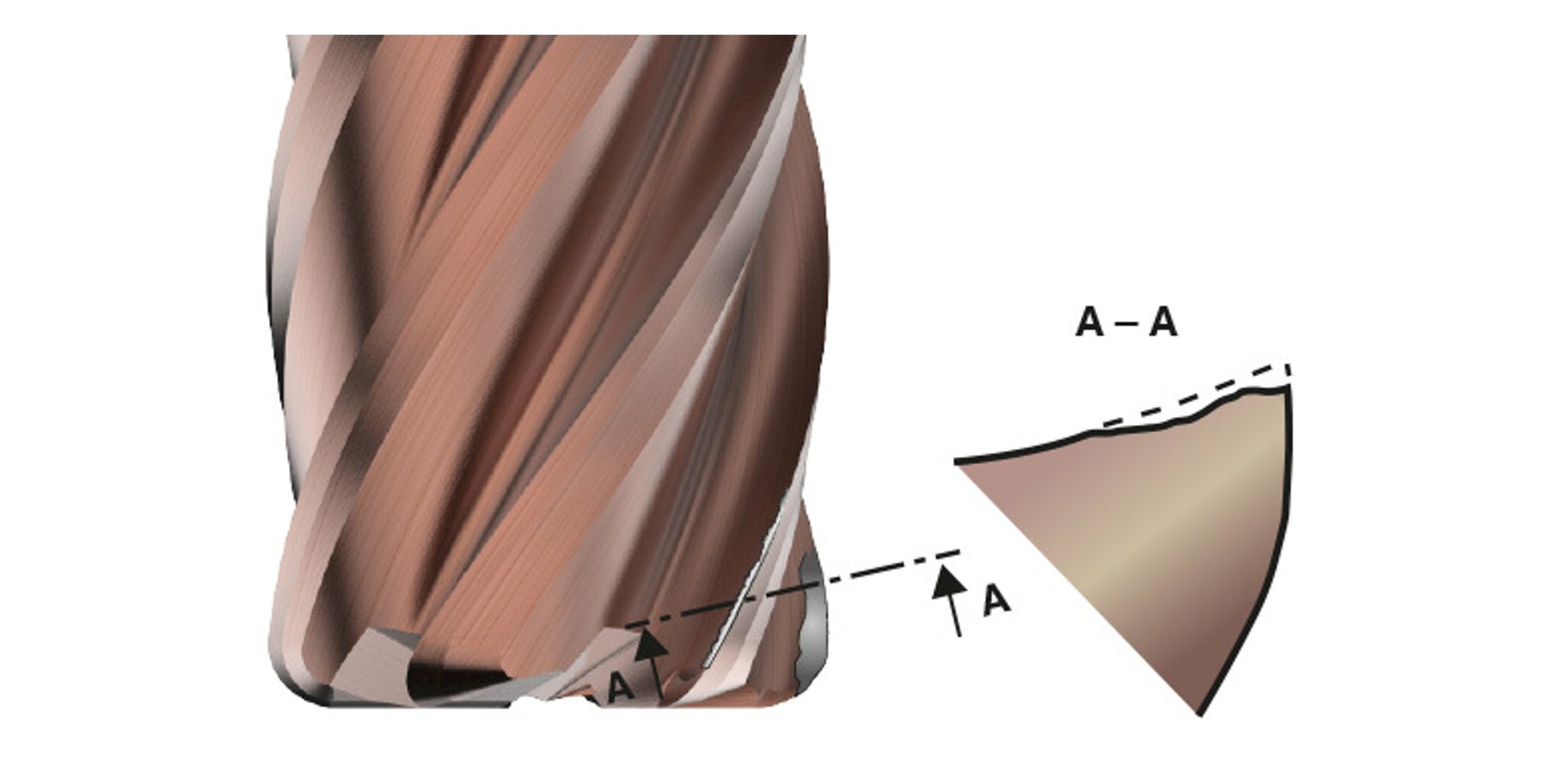
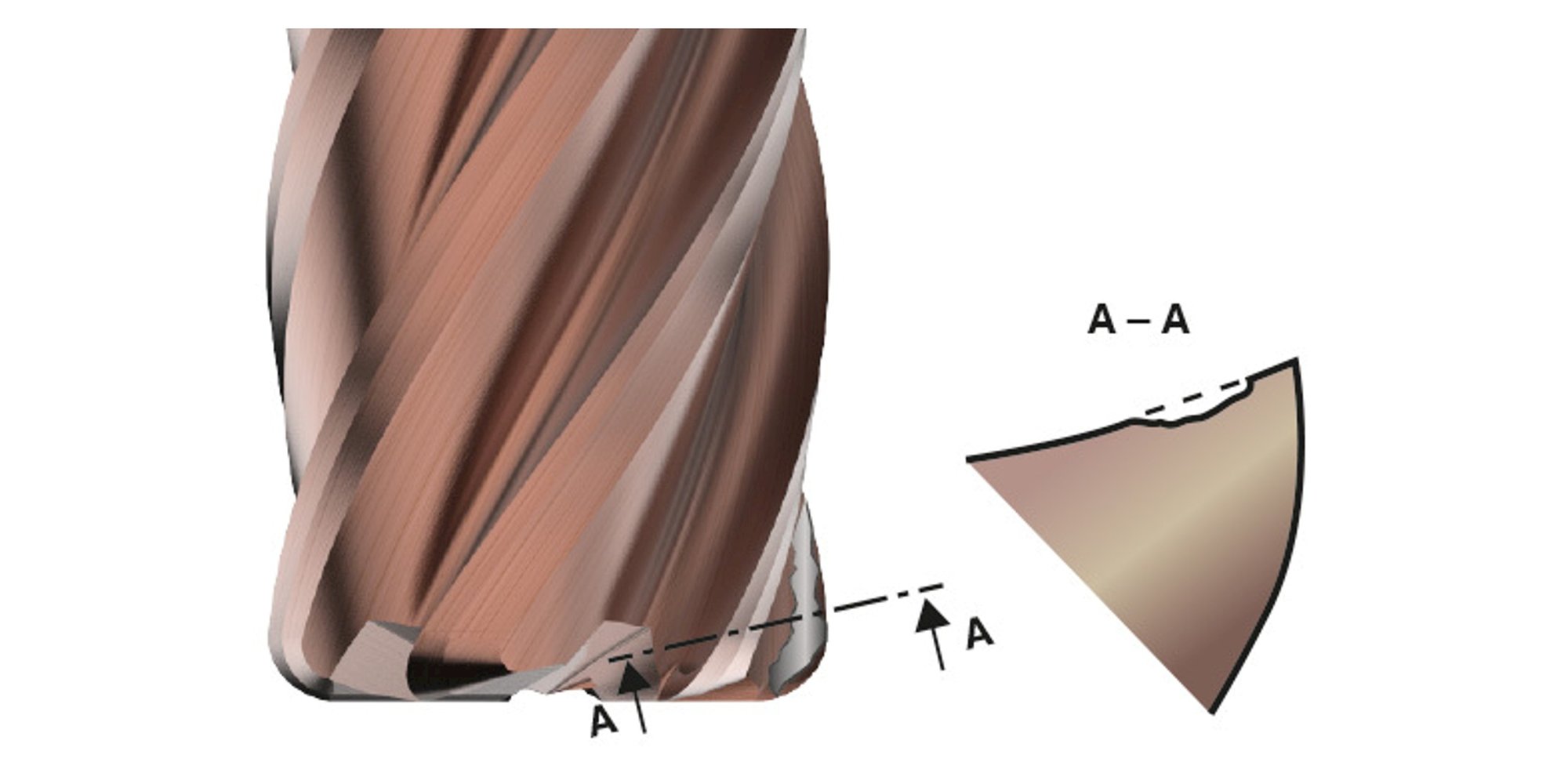
Stair-faced wear happens on the rake face of a cutting tool, right where it meets the flank face along the cutting edge. This kind of wear shows up because of the high friction and heat that build up in the cutting zone, especially when the tool stays in constant contact with the workpiece. Over time, this leads to accelerated erosion or abrasion at that point, forming a noticeable groove or notch on the face of the tool.
- Increase coolant supply
- Reduce feed/speed rates
- Use appropriate tool geometry
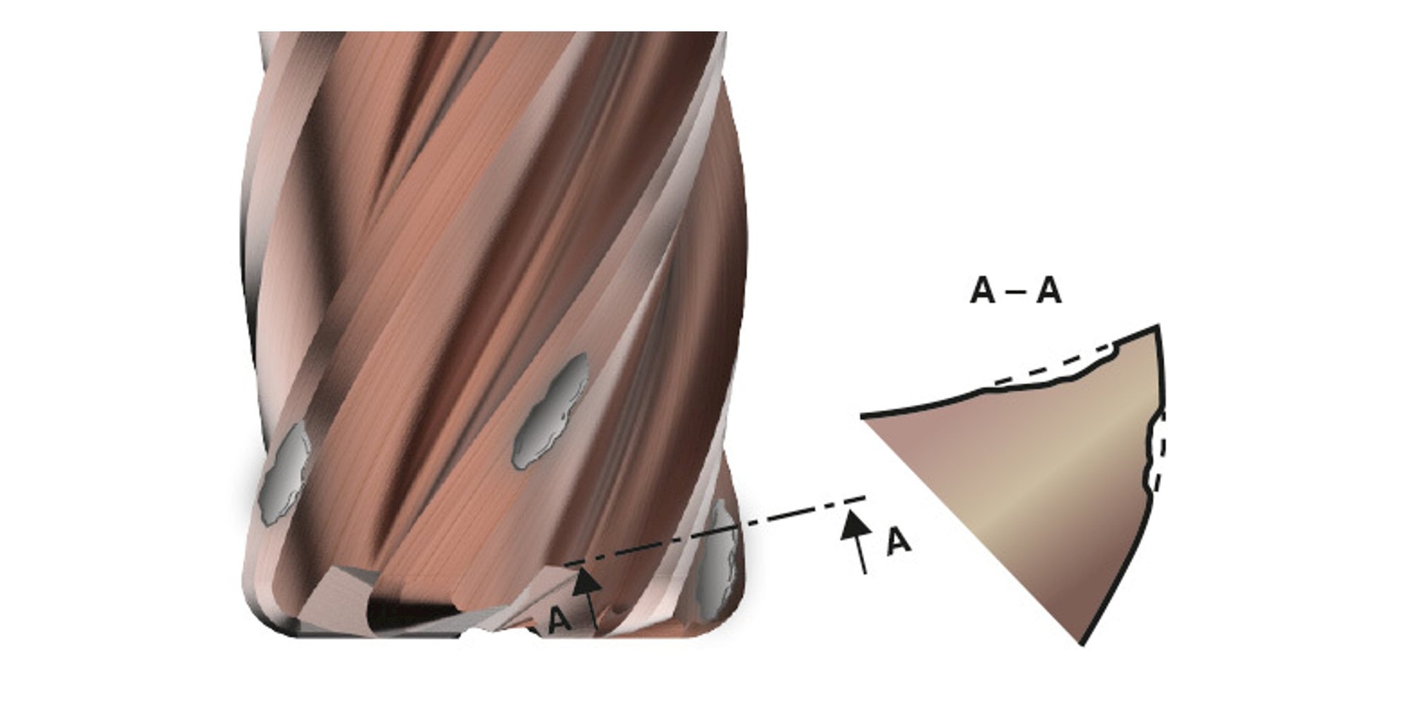
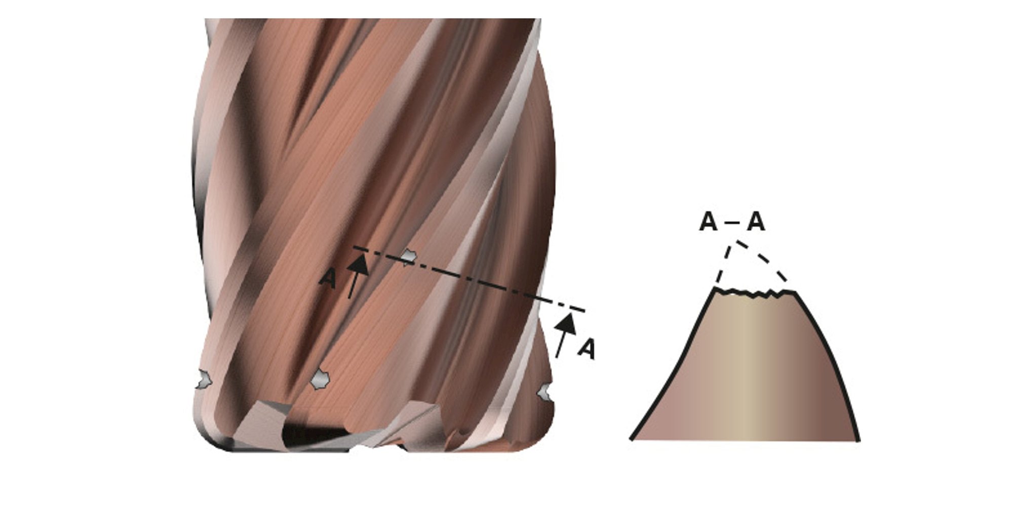
Flaking is the loss of small fragments (flakes) from the surface of a cutting tool. It is more noticeable on coated tools, where thermal and mechanical stress causes cracks in the coating, leading to delamination. Common causes include sticky workpiece materials or incorrect cutting parameters.
- Optimize cutting parameters
- Maintain stable machining conditions
- Increase coolant/lubrication
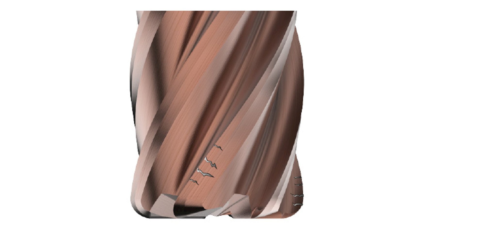
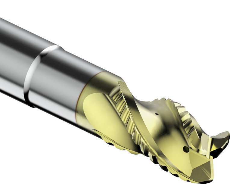
Comb crack wear is damage that appears on the cutting edge or rake face of a tool as a series of crack-like lines resembling the teeth of a comb. These cracks usually form along the cutting edge and are caused by heat during interrupted cutting operations, which are common in milling.
- Optimize cutting parameters to reduce heat generation
- Use coated tools with better thermal resistance
- Increase coolant/lubrication
- Avoid high cutting speeds or feeds
- Use a more suitable substrate

Non-uniform chipping occurs at random points along the cutting edges, often starting with tiny cracks caused by mechanical or thermal stress. It’s usually triggered by things like interrupted cutting or vibration, an unstable setup, hard spots on the workpiece, or chips getting re-cut. These issues create stress points that gradually wear down the tool, leading to uneven damage.
- Improve fixturing to reduce vibration
- Optimize cutting parameters
- Increase coolant/lubrication
- Inspect tools regularly for early cracks
- Check workpiece material for hardness variations
A catastrophic fracture is, as the name implies, catastrophic. Complete tool breakage can be caused by a variety of reasons. Mostly mechanical overload on the cutter, excessive vibrations, chip evacuation problems or a previous wear pattern being ignored.
This type of failure not only damages the tool but can also affect the workpiece, machine or even pose safety risks to operators if it occurs during high-speed operations.
- Improve set-up to reduce chatter and vibrations
- Check the run-out of the tool
- Keep the length short
- Make sure you are using the correct tool holder
- Adjust cutting parameters to reduce load on the tool
- Make sure chips are evacuated correctly
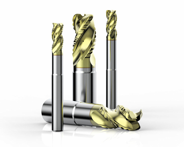
So, you think you have come to the end of your tool’s life. But not quite – let’s smoothly transition to reconditioning. Reconditioning means regrinding, reapplying edge preparation or treatment and recoating a milling cutter in such a way that the original performance can be guaranteed, a process that can be done up to three times.
Once your tool has reached this stage, you can reach out to us for more information:
Inline Content - Gridded Links
Tags: 'reconditioning'
Max links: 1